


A full polishing range.
From cutting and one-step correction to final finishing.
Specialist chemistry. Expert application.
 QUARTZ99 / CERAMIC BASE COAT
The foundation of your coating system.
A layerable quartz base coat designed for mechanical protection. Pair it with a suitable top coat to create the final finish.
For application by NANOLAB certified installers only.
Four formulas. Extended working time. Find the coating for your finish.
Explore the BEAST family of ceramic coatings.
Find the coating for each exterior surface.
 PPF & VINYLGLOSSProtection for glossy films and wraps.Discover
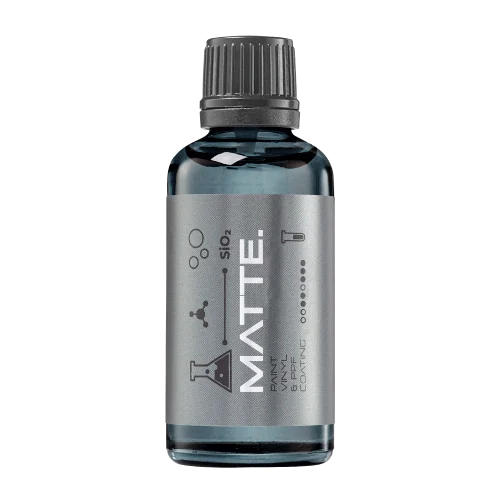 MATTE & SATINMATTEProtection that respects the finish.Discover
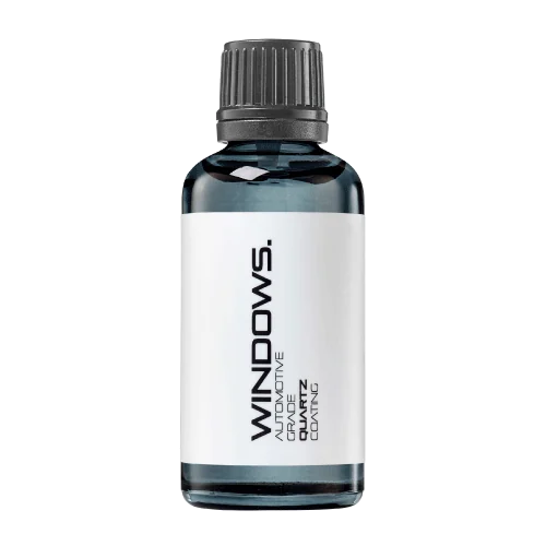 GLASSWINDOWSExplore dedicated glass protection.Discover
 WHEEL PROTECTIONWHEELSA dedicated coating for your wheels.Discover
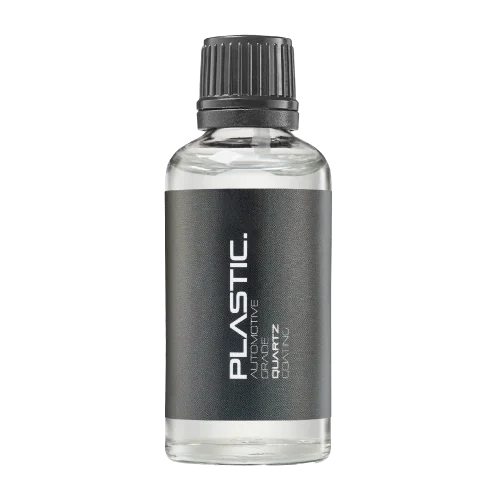 TRIM PROTECTIONPLASTICProtection for plastic surfaces.Discover
Dedicated care for the surfaces inside.
 LEATHER SURFACESLEATHERDiscover NANOLAB leather protection.Discover PLASTIC SURFACESPLASTICProtection for interior plastic surfaces.Discover TEXTILE SURFACESFABRICExplore the latest fabric formulation.Discover
Spray protection, maintenance and upcoming wash products.
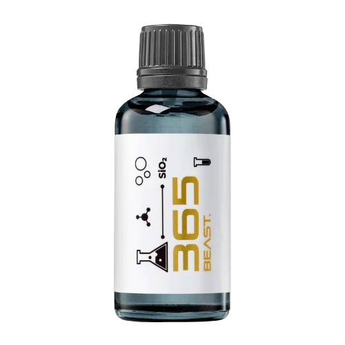 MAINTENANCEBEAST 365Explore the BEAST maintenance range.Discover
Next in washing, cleaning & care.
Ceramic protection for boats and yachts.
An easy-to-apply ceramic coating with an established track record on boats and yachts around the world.
Results vary with surface preparation, exposure and maintenance.
Read 50 MARINE guides →Explore MARINEProtection for the surfaces you live with.
A look at what we’re developing.
From cutting and one-step correction to final finishing.
A wider range for professional vehicle care.
Taking shape alongside BEAST & MATRIX.
Practical guidance for your next coating project.
Explore all guides →
Use microscope focus stacks to document coating defects while retaining original focal planes, scale information and the limits of the image.
Updated · NANOLAB Knowledge

A focus-stacked microscope image can combine details from several depths into one sharp view that never existed as a single optical plane. It is useful for presenting a coating defect, but should not erase the evidence needed to understand where each feature appeared.
Microscope depth of field limits how much vertical structure appears sharp at once. Leica’s microscopy guidance explains how digital methods can extend the apparent in-focus region. Preserve the original frames as well as the composite: a presentation image and a measurement record serve different purposes.
Start with an overview locating the defect on the panel. Add a lower-magnification view connecting the marked location to the microscopic field. Without that chain, a close-up may be impossible to relocate after cleaning or further testing.
| Field | Purpose |
|---|---|
| Sample and location | Connect the image to the affected part |
| Objective and camera setup | Identify the optical configuration |
| Scale calibration | Support lateral measurements |
| Frame sequence and focus spacing | Preserve the sampled focal range |
| Software and settings | Make processing reviewable |
| Original frames | Allow ambiguous edges to be checked |
A feature becoming sharp at a different focus setting is an observation, not automatically a calibrated coating-thickness measurement. Optical geometry, transparent layers and instrument mechanics can affect interpretation. A quantitative thickness or depth claim requires an appropriate validated method and reference.
Similarly, a composite alone cannot establish whether a particle is embedded or resting on a surface. Preserve the sample, examine the focal sequence and identify what additional evidence would distinguish the possibilities. Avoid destructive follow-up until the relevant observations are recorded.
Reflected highlights, low-contrast regions and steep features can produce misleading boundaries during stacking. If a line appears only in the composite, mark it as uncertain rather than using it as a precise defect perimeter.
For example, a bright ring around a suspected inclusion may shift between focal planes. A composite could make that ring appear continuous. The source frames help a reviewer decide whether the ring describes the sample or the assembly process. This is an illustrative imaging problem, not a NANOLAB test result.
Label stacked images as stacked. Tie the scale bar to calibrated image dimensions; never paste a bar from another magnification or resize it independently. State relevant cropping, contrast adjustment and compositing. Include a single-plane view beside the composite when it resolves an important ambiguity.
Retain an unedited copy and give processed versions distinct filenames. A reviewer should be able to move from the published figure back to the original frames and sample location. A strong report distinguishes what is visible, what was measured and what remains unresolved.
These sources support the identified technical concepts. The planning examples in this guide are illustrative and are not NANOLAB performance test results.
Discuss your surface and intended use with NANOLAB. Follow the current instructions for the exact product when planning application and care.

A microscopy image needs scale and specimen information to be meaningful. Magnification alone may become misleading when an image is resized.
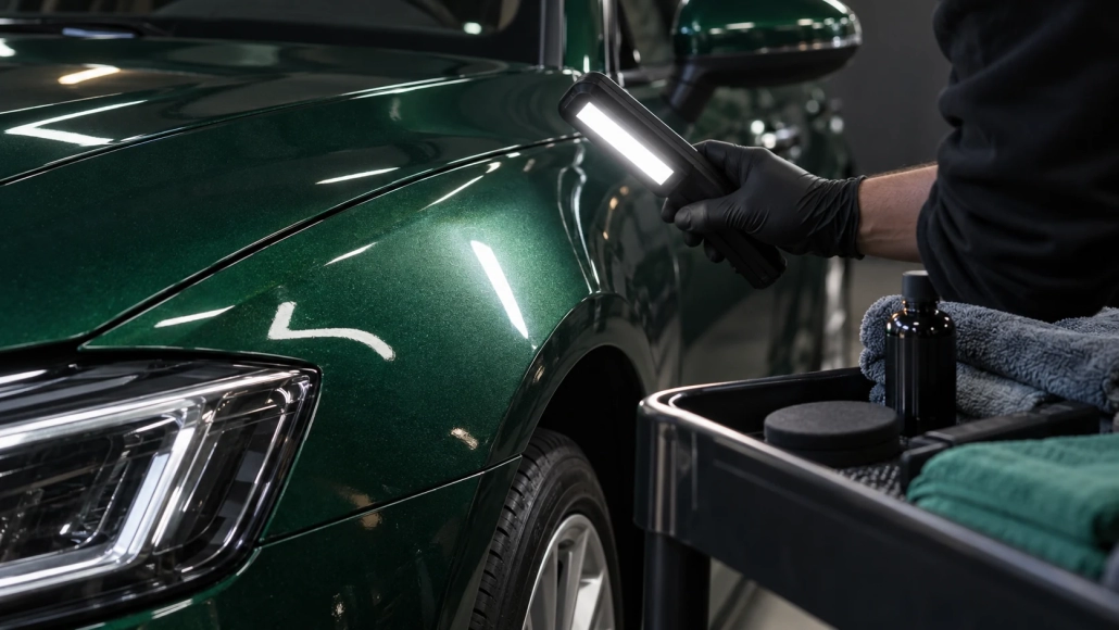
Keep focus, magnification and camera distance fixed when comparing surface reflections, especially in close photographs of coated paint.
 Water Spots Appearing Only after Driving: Trace the Water Source